 Check out the details here: http://www.thingiverse.com/thing:5020
Friday, December 3, 2010
Wednesday, December 1, 2010
PLA: Highly Recommended
I purchased PLA from Makerbot and MakerGear, and am happy to say that PLA has definitely lived up to the hype.

I've had no noticeable warping, even when printing the largest part sizes possible on the Makerbot, like these planetary gear quarters that are part of a prototype for one of our Senior Design groups. PLA forms a harder part than ABS, which is preferable for sharp edged parts such as these.
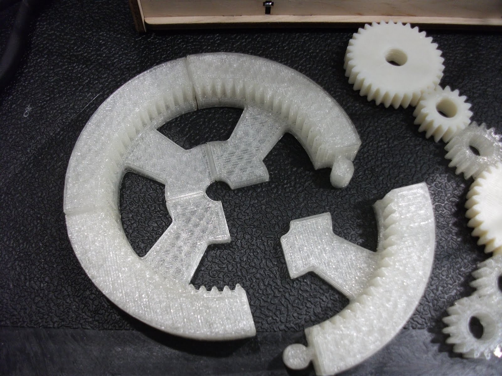
PLA is a bit more demanding than ABS, in that as it melts it goes through a "gummy bear" stage, which can jam in the nozzle. When warming up, it requires a bit of finesse that ABS didn't need, in order to get started. I use the same temperature settings as with ABS (225C target), since the material I received has a declared melting temperature a degree higher than what I observed with ABS (ABS 209C, PLA 210C). This allows for the temperature swings I get on the extruder, and caused no observable issues. When the extruder warms up to 225C, I clear the drippings, which can be substantial, then I loosen the tension screw on the MK5, and manually press the filament in to the extruder a couple inches, which clears out some of the melted PLA in the barrel. I then tighten the tension bolt and run the extruder motor from the control panel for 15-30 sec to make sure I'm getting a nice extrusion. I clear the extruded gunk, then start the print.
Between prints, I've noticed that if I let the extruder cool, then heat up again, it has a tendency to create a "gummy bear" plug in the extruder barrel. This can be pulled out and clipped off, as in the pic below, or just wait 5 min after hitting target temp to make sure the "gummy" has melted to goo before printing the next part.
 This is what happens when you get impatient and run the hot PLA part under cold water, rather than letting it air cool. I then popped it off with a pair of vice grips, and the long-suffering orange acrylic plate gave up the ghost. I had another orange plate, so I wasn't forced to mill something from aluminum , although that would probably be a good idea, longer term. When I put the new plate on, I tested printing on blue painter's tape, and that's working very nicely.
Wednesday, November 3, 2010
Crossroads
I've come to the tentative conclusion that the effective print size is limited to a base of about 2 inches square for colored ABS plastic without a heated print bed. "Natural" ABS is somewhat more forgiving, but the shrinkage of the material is still a significant concern. There are a couple options. I've ordered 5 lbs. of PLA from Makerbot and am looking forward to seeing how this material works out. I do have the heated print bed for the Cupcake, but I've not soldered it together, mainly due to having better things to do than painstakingly hand solder the many surface mount resistors in order to get it assembled.
Here's a picture of Marvin Mk2, a little bot that the MSU Robotics group designed and printed, other than the electronics and a few screws. The Mk1 is documented on Thingiverse, and Mk2 adds a servo to allow positioning of the optical sensor independent of the bot's movement direction. Currently Marvin motors forward until an obstacle comes within 20cm or so, then he turns left until the way is clear. I call it the hacky-sack program. There are plans to add maze solving to his programming, but even with the simplest of control algorithms, folks young and old are fascinated. Here's a test video of Mk1.
 We (MSU's McCoy Engineering School) took the Makerbot, robots Marvin and Charlotte to the Austin Science and Engineering Expo and to the MSU Majors Fair and they were all a huge hit. Even though the Cupcake refused to talk to my laptop at the Expo, I think we sold a few Makerbots, and probably could have sold more if they had sent me the marketing post cards that I requested! Ahh, well, with the endorsement of the mayor of New York City, who needs engineering schools, eh? (/wink)

 We (MSU's McCoy Engineering School) took the Makerbot, robots Marvin and Charlotte to the Austin Science and Engineering Expo and to the MSU Majors Fair and they were all a huge hit. Even though the Cupcake refused to talk to my laptop at the Expo, I think we sold a few Makerbots, and probably could have sold more if they had sent me the marketing post cards that I requested! Ahh, well, with the endorsement of the mayor of New York City, who needs engineering schools, eh? (/wink)
Wednesday, September 15, 2010
Pictures and Settings Update
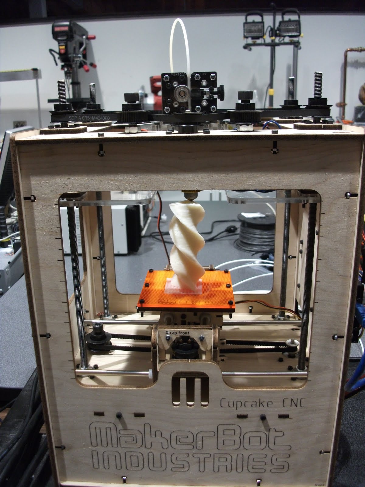
Hoeken's Twisted Form Study:
I can confirm that the PID settings work as advertised:
P: 11
I: 0.35
D: 110
Heat up time to 220C is 9 minutes, stablized at ±4C within 12 minutes.

Datafusions' ball(ball()) again, in creepy fleshtone: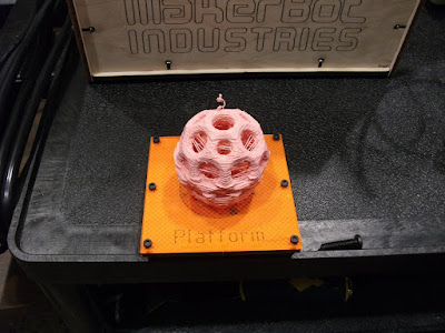
I can confirm that the PID settings work as advertised:
P: 11
I: 0.35
D: 110
Heat up time to 220C is 9 minutes, stablized at ±4C within 12 minutes.
I've settled on Skeinforge settings:
Carve:
0.35 layer thickness
1.7 Width/Thickness
Speed:
30 Feedrate
230 Flowrate
Thursday, September 9, 2010
Mk5 Temperature Settings
Here are some working temperature settings for my Mk5 Plastruder:
P: 7.0 I:0.34 D: 36.0
This produces a warmup time to 230C of around 9 minutes and temperature swings 230+8-15 (ish) for my Mk5.
I'm warming up to 230C manually, printing rafts at 235C and the rest of the part at 230C which is producing acceptable print quality.
I'd love to be able to reduce the swings drastically, since that should improve surface finish, but its far more critical that its printing reliably!
Friday, September 3, 2010
Mk5 Torture Test & Calibration
To put the Mk5 through its paces I decided to print datafusions' ball(ball()). As can be seen, about half way through, the cumulative error in Z calibration caused a major shift. I let it finish printing, partly just to see if it would and mainly to continue testing the Mk5 extruder. It finished in 1 hour and 34 minutes, with the extruder passing with flying color (beige).
 I then set about learning to calibrate the Z axis and learned a good deal about replicatorG, various calibration parts and skeinforge settings. It seems that simply setting the "carve" to 0.39 or 0.40 has reduced or resolved the issue. Each Cupcake is somewhat unique, so YMMV. I created a single walled, open, 10 & 20mm stairstep part as my own calibration piece and I'll have to upload it to thingiverse, soon. Note: Uploaded here.
Here are some of the fruits of the bot, so far:

Mk5: Plastruder Messiah*
* After a few, relatively minor improvements.


Although I was warned by the web site that it might be a few weeks before the Mk5 was delivered, I was happy to see it arrive within a few days. After an uneventful assembly and installation, I fired up replicatorG and pulled up the control panel to test the temperature and then extrusion capabilities.
Minor Improvement 1: For some odd reason, the Mk5 is glued (as was the Mk4) onto a piece that is bolted to the Z axis plate. This means that the glue is holding the Mk5 in place, which struck me as an invitation to pop loose at some inconvenient time. I simply drilled the holes wider and used a larger bolt and nut to bolt both pieces (on each side) at the bottom of the Mk5 directly to the Z axis plate. Since I had them handy, I used 1/4" machine screws and nuts, but a metric size would be more in keeping with the theme.
Minor Improvement 2: As soon as the temperature of the plastruder passed 185C, the solder joints bringing power to the resistors melted and the heater wires popped off. After some mucking about I settled on stripping the plastic off of some handy crimp rings, making some short shunts from a piece of #14 solid copper wire with a crimp ring on each end, crimping another ring to the ends of the feed wires, then using #2 bolts and nuts (again, metric would be politically correct) to bolt the rings directly onto the ends of the resistors, which come with handy #2 sized holes already in them. This avoided worrying about high temperature solders and how long the joints would hold.
Minor Improvement 3: Bolt the thermal cape to the top of the arch using the assembly bolts, and between the two layers at the bottom of the arch assembly. The fact that the Mk5 comes with its own cape strikes me as implying that perhaps it's a superhero rather than the messiah, but I'll leave my post title as is.
After this point, I'm happy to report that the Cupcake CNC began extruding its little heart out. I still had the heater PID set for the MK4, so to compensate, I simply set the temperature target at 240C. The temperature swung down to 215-ish at times, but ABS seems to melt down to about 208 or so, so I left the temperature adjustment to another day.
Issue2: Updates
After the MK4 Plastruder showed its unreliabilities, I decided to try to eliminate as many variables as possible to figure out where the problems really came from.
First step: Updating the firmware of both the motherboard and the extruder controller. This turned out to be more of an odyssey than expected, but I finally got the Cupcake CNC connected to a PC that had an internet connection, the correct java version to run replicatorG and the appropriate python version all at once. I then set about updating the firmware and ran across a number of head-scratchers in the wiki. Now that I reviewing the wiki, it appears that I was on a different page than the ones I'm searching up now, so it's likely operator error. For my own reference, at least, here's the procedure that worked:
Motherboard:
- On a PC that has an active internet connection and is running replicatorG
- Select the option to update the motherboard firmware
- Follow instructions here until ready to press the Upload button
- Press Upload button on replicatorG and immediately after, press the physical Reset button on the motherboard
- Wait for the upload to complete and confirm
Extruder Board:
- On a PC that has an active internet connection and is running replicatorG
- Disconnect the USB2TTL cable from the Cupcake CNC motherboard
- Connect theUSB2TTL cable into the extruder board's six-pin serial header, next to the reset button
- Select the option to update the extruder firmware
- Follow instructions here until ready to press the Upload button
- Press Upload button on replicatorG and immediately after, press the physical Reset button on the extruder board
- Wait for the upload to complete and confirm
- Disconnect the USB2TTL cable from the extruder board
- Connect the USB2TTL cable into the Cupcake CNC motherboard's six-pin serial header
Once the firmware was updated, I took apart the MK4 plastruder and installed the MK5 Drive Gear Upgrade Kit and printed a part. . .or, rather, didn't print a part or even do much more than extrude a few inches of material. After fiddling with the whole setup for a number of hours I came to the conclusion that, at least in my case, adding the MK5 drive gear made the MK4 platruder nearly unusable, rather than simply rather unreliable. I couldn't get the MK4 idler/pinch wheel to reliably hold tension against the MK5 drive gear.
At this rather frustrating point I realized that my suspicions (from the start of assembly) about the unreliability of the MK4 plastruder were confirmed. As it stood, the Cupcake CNC's Cartesian drive system was useable, reliable and precise enough for prototyping work, but the extruder system was going to require a re-design.
Before I fired up SolidWorks and Mastercam and went to work, I decided to look around at options people have been coming up with around the makersphere. I lean heavily toward metal based solutions, being that I'm a machinist and having some experience now with the stresses the device was going to have to handle. As I was looking at several excellent designs that folks are using and considering the options, lo and behold, the MK5 was released.
After considering calling up Makerbot and demanding a replacement or at minimum an upgrade price, I decided that the department could affort to subsidize their work and just went ahead and ordered the MK5 plastruder.
Sunday, August 8, 2010
Issue 1: Makerbot Cupcake CNC Plastruder Mk4
The Makerbot Plastruder Mk4. Not exactly the most popular thing around the makersphere, and unfortunately, deserving of its reputation.


 This nearly worked, and fortunately as I tested the fit by trying to jam the filed double idler into the pulley, the top of the pulley popped off. I removed the bearing, removed the pulley top, and refit the bearing, leaving enough space for the filed double idler. After messing with different washer configurations to get the idler to sit in the newly expanded pulley, everything came together.
Note the radial lines drawn on the idler wheel assembly. In my not so humble opinion, it's not an optional step. This is a suggestion that's made too late in the instructions: after it's already bolted inside its enclosure. I also marked the enclosure itself with two reference lines so that the operator can near instantly see if the filament is feeding.
First, the controller board is mounted directly in front of the most important part of the entire machine. . .the location the operator most needs to see at all times: the pinch wheel and idler feeding filament (or not).
As mentioned in the assembly instructions, step 15, my answer was to move the board. The top left corner of the case wall has a space seemingly designed it. Simply drill a few holes for mounting and cable feeding, crimp on some extra lengths of wire, twisted neatly to reduce EMI, and voila.
All well and good until you print a bit and run into the Achilles heel of the design: the idler wheel. Thankfully there are some pointers in the assembly instructions to help with this as well. In the instructions, this discussion is referenced, although there is a caution not to use the method with the Mk4. This is probably because the doubled idler wheels are wider than the pinch pulley that's included with the Mk4. I decided to file the edges of the doubled idler wheel to a bevel so that the assembly would fit into the pulley.
This nearly worked, and fortunately as I tested the fit by trying to jam the filed double idler into the pulley, the top of the pulley popped off. I removed the bearing, removed the pulley top, and refit the bearing, leaving enough space for the filed double idler. After messing with different washer configurations to get the idler to sit in the newly expanded pulley, everything came together.Note the radial lines drawn on the idler wheel assembly. In my not so humble opinion, it's not an optional step. This is a suggestion that's made too late in the instructions: after it's already bolted inside its enclosure. I also marked the enclosure itself with two reference lines so that the operator can near instantly see if the filament is feeding.
 I was considering various options to improve the grip of the drive pulley and happened across a reference to the MakerBot site, where the problem is addressed. I've ordered the Mk5 Drive Gear Upgrade Kit, which should feed filament better and have less issues with the double idler setup, if I'm eyeballing it right. To tell the truth, I'm a little annoyed that this upgrade wasn't automatically included in the purchase, or I wasn't somehow notified that it was really, really likely I was going to want to spend an extra $10 on it. . .which I would have gladly done.
So, after re-assembly, the Plastruder Mk4.1 is working as well as it is likely to, which is to say that it regularly strips a bite out of the filament whenever there is back pressure on the extrusion due to the nozzle being too close to the part, for any of a good number of common reasons. The filament then stops feeding, ruining the part and requiring the operator to back the filament completely out, cut to a virgin section, feed it back in, test the extrusion, then restart the part. Hopefully the Mk5 upgrade will help with this.
Thursday, August 5, 2010
Made: Makerbot Cupcake CNC
Thanks to a great deal of help from summer intern Summer, we have our brand spankin' new Makerbot Cupcake CNC 3D printer assembled and tested. I've been looking forward to this for more than a year and am thrilled to see it all coming together at last!
 The full photo album of the build is here.
 Early in the Y stage assembly
 X & Y stages assembled
 Z stage leveling
 Everything assembled!
 Opus 1: "Don't Eat the Cotton Candy"
 Summer aligning the first print
 First Print: Cid's shot glass. . .well, at least a third of it printed.
 More printing goodness
Monday, July 5, 2010
Meth(ane) Production Apparatus
I had the opportunity to help with a fun little project related to a UGROW (Undergraduate Research Opportunities and Summer Workshop) grant for the Biology department. The student is researching the feasibility of speeding up the methane gas production cycle using targetted methanogens to convert food service waste into a renewable fuel source.

The design and documentation of the apparatus also served as my final project for the Solid Modelling class I was taking. Files are available in SolidWorks format, drop me a line. Since I'm doing the work in preparing the laboratories and designing many of the projects here at the school of engineering, I decided I might as well get the degree. It'll take a number of years, since I'm only taking a class at a time, or so, but I don't mind .
The design and documentation of the apparatus also served as my final project for the Solid Modelling class I was taking. Files are available in SolidWorks format, drop me a line. Since I'm doing the work in preparing the laboratories and designing many of the projects here at the school of engineering, I decided I might as well get the degree. It'll take a number of years, since I'm only taking a class at a time, or so, but I don't mind .
YES Camp
June was a busy month for us around here. We held a week-long Young Engineer's Summer Camp for high school juniors and seniors here at the Midwestern State University, McCoy School of Engineering. It was quite a success.

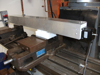
Teams of students explored engineering design challenges through LEGO Robotics, were introduced to all of the Engineering labs, such as the Thermofluids' wind tunnel below, and participated in interactive sessions involving disciplines used in Engineering: Math, Physics and Chemistry.
Gulliver's Traversal: Assembled
I just realized that I haven't posted an update of the assembled Gulliver. Here he is (so far)in all his one axis'd glory. I taped a measuring tape to him and attached a simple aluminum pendulum.

The next step is to re-design the Z-axis (vertical) arm assembly, since it's become apparent that I was overly optimistic in my initial design, then to fabricate it!
Wednesday, May 26, 2010
Gulliver's Traversals II
After getting the electronics soldered, assembled and tested, the mechanical parts provided their own set of challenges. Here's Gulliver's assembled traverse arm, upside down.
 One of the interesting challenges was to create a system where the traverse arm would move along the threaded rod. I decided to go with a design concept I've seen online (but can't currently locate the link) that included melting the "teeth" into plastic blocks to create a backlash-free plastic "nut" that's then mounted on a carriage made with bearings. Here's the final "nut" being formed, with a number of the test pieces I did to get to the final. I'm using 1/2 inch diameter - 10 thread per inch ACME thread rod. After experimenting, I realized the maximum effective width of the "nut" is limited to around 1/2 inch before it simply grabs the thread rod, causing too much friction. To make the "nut," I drilled a 15/32 inch hole between two pieces of HDPE plastic plate stock, squeezed the thread rod between them in the vice, then heated the upper tip of the rod with a braising torch until the plastic started melting. I then sqeezed the vice harder and let the whole thing cool, forming the teeth exactly around the rod.
 Here's the assembled carriage. the "nut" piece can bee seen peeking out from between the bearings.

I ended up going with simple tubing to connect the motor to the thread rod because the end of the rod is just enough out of round to cause the motor to rattle back and forth when I tried connecting them with a rigid brass fitting. The jury is out on whether this is a workable long term solution. We'll see.

Here's Gulliver's arm assembled and ready for testing (resting upside down).

 One of the interesting challenges was to create a system where the traverse arm would move along the threaded rod. I decided to go with a design concept I've seen online (but can't currently locate the link) that included melting the "teeth" into plastic blocks to create a backlash-free plastic "nut" that's then mounted on a carriage made with bearings. Here's the final "nut" being formed, with a number of the test pieces I did to get to the final. I'm using 1/2 inch diameter - 10 thread per inch ACME thread rod. After experimenting, I realized the maximum effective width of the "nut" is limited to around 1/2 inch before it simply grabs the thread rod, causing too much friction. To make the "nut," I drilled a 15/32 inch hole between two pieces of HDPE plastic plate stock, squeezed the thread rod between them in the vice, then heated the upper tip of the rod with a braising torch until the plastic started melting. I then sqeezed the vice harder and let the whole thing cool, forming the teeth exactly around the rod.
 Here's the assembled carriage. the "nut" piece can bee seen peeking out from between the bearings.
I ended up going with simple tubing to connect the motor to the thread rod because the end of the rod is just enough out of round to cause the motor to rattle back and forth when I tried connecting them with a rigid brass fitting. The jury is out on whether this is a workable long term solution. We'll see.

Here's Gulliver's arm assembled and ready for testing (resting upside down).

Tuesday, May 25, 2010
Gulliver's Traversals I
Finally, and at long last, progress on a project related to personal manufacturing! Meet Gulliver, well, Gulliver's traverse arm, anyway. He has a long way to go, but at least there's something to show for all the work! Once he's somewhat further along, Gulliver will be assisting with Mechanisms, Thermofluids and Kinematics classes and eventually, I hope to fit him with an extruder to make him into a 3D plotter.
 Here's Gulliver's traverse arm upside down, being tested, with the controller box and the Mach3 software I'm using to run it. Artsoft's Mach3 software is a state of the art machine control application, extremely configurable and has a free downloadable version that you can use indefinitely. Highly recommended!

His "central nervous system" is finished up and all four axis motors hooked up and tested.
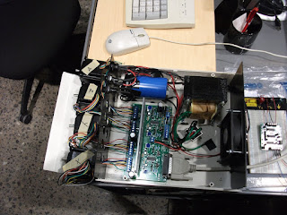
All hooked up, but nowhere to go. Here's the finished motor controller.

Here's Gulliver's traverse arm upside down, being tested, with the controller box and the Mach3 software I'm using to run it. Artsoft's Mach3 software is a state of the art machine control application, extremely configurable and has a free downloadable version that you can use indefinitely. Highly recommended!Not too long ago, Gulliver started out as merely a printed circuit board, entirely bare. I forgot to take that picture, so here's Gulliver's "central nervous system" with just the first resistors and capacitors soldered in. This kit is the HobbyCNC Pro Driver Board package, and I can wholeheartedly recommend it to anyone willing to do the soldering and assembly. It's very low cost, high quality and comes with clear directions.

After quite a bit of squinting and soldering later, his main motor controller board is ready.
His "central nervous system" is finished up and all four axis motors hooked up and tested.
All hooked up, but nowhere to go. Here's the finished motor controller.
Wednesday, April 28, 2010
Repairs and Remakes
All week it's been fixing and shoehorning, shaving down or shimming up. I came up with a novel (for me) way of making small grooves with a hacksaw blade. The students were celebrating that I was going to become rich from my invention until I reminded them that a hacksaw blade costs a buck.
 A number of hydraulic motors had to be re-bracketed and re-pulleyed and a hydraulic friction testing piston needed reinforced. So it has gone.

 A number of hydraulic motors had to be re-bracketed and re-pulleyed and a hydraulic friction testing piston needed reinforced. So it has gone.
Wednesday, April 21, 2010
PCB Opus 1
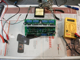
In all these years, although I've done minor repair soldering here and there, I'll have to admit to never having populated a PCB with components. I'm beginning work on a pendulum traverse system for one of the professors and decided it was a good opportunity to save several thousand dollars by doing the microcontroller and motor control board from open source hardware. In addition, its a great opportunity to begin creating my first microcontrolled system. I have a backlog of 5 or 6 projects already, this being the simplest!


I'm using an Arduino Deumilanove and purchased Adafruit's Motor Shield, which I highly, highly recommend! The shield comes as a PCB and components and you have to solder them in yourself. The instructions are clear and very complete. I'm fortunate to have been able to simply head over to Radio Shack and buy the tools for a basic soldering setup, and by following the picture by picture instructions, the soldering took less than an hour and the board is running the sample code for DC and stepper motors like a champ.

Friday, April 16, 2010
Busy Busy
It's been the busy time. Many projects all come together for the end of the year. The seniors are all working on (i.e. frantically trying to finish) their Senior Design Group Projects.
 These are parts for a motorcycle "landing gear" project that is designed to assist riders who have difficulty with balancing. "Why should someone with balance problems be riding a motorcycle?" you ask. Perhaps those who have fallen off of one previously, but who still love to ride.


 These are parts for a motorcycle "landing gear" project that is designed to assist riders who have difficulty with balancing. "Why should someone with balance problems be riding a motorcycle?" you ask. Perhaps those who have fallen off of one previously, but who still love to ride.
Another team is working on a torsion testing machine that will twist samples to destruction, measuring the torque required and the angles at which the samples pass from one state to another.
Not to be outdone, the faculty have been asking for things as well. Here's one of the more exotic, a set of clear cast acrylic flanges with brass inserts that will be used to study fluid dynamics. The prof. couldn't find what he wanted, so he asked me to design and fabricate them.


Subscribe to:
Posts (Atom)
