Monday, July 5, 2010

Meth(ane) Production Apparatus

I had the opportunity to help with a fun little project related to a UGROW (Undergraduate Research Opportunities and Summer Workshop) grant for the Biology department. The student is researching the feasibility of speeding up the methane gas production cycle using targetted methanogens to convert food service waste into a renewable fuel source.


The design and documentation of the apparatus also served as my final project for the Solid Modelling class I was taking. Files are available in SolidWorks format, drop me a line. Since I'm doing the work in preparing the laboratories and designing many of the projects here at the school of engineering, I decided I might as well get the degree. It'll take a number of years, since I'm only taking a class at a time, or so, but I don't mind .


YES Camp

June was a busy month for us around here. We held a week-long Young Engineer's Summer Camp for high school juniors and seniors here at the Midwestern State University, McCoy School of Engineering. It was quite a success.


Teams of students explored engineering design challenges through LEGO Robotics, were introduced to all of the Engineering labs, such as the Thermofluids' wind tunnel below, and

participated in interactive sessions involving disciplines used in Engineering: Math, Physics and Chemistry.

Gulliver's Traversal: Assembled

I just realized that I haven't posted an update of the assembled Gulliver. Here he is (so far)in all his one axis'd glory. I taped a measuring tape to him and attached a simple aluminum pendulum.


The next step is to re-design the Z-axis (vertical) arm assembly, since it's become apparent that I was overly optimistic in my initial design, then to fabricate it!

Wednesday, May 26, 2010

Gulliver's Traversals II

After getting the electronics soldered, assembled and tested, the mechanical parts provided their own set of challenges. Here's Gulliver's assembled traverse arm, upside down.

One of the interesting challenges was to create a system where the traverse arm would move along the threaded rod. I decided to go with a design concept I've seen online (but can't currently locate the link) that included melting the "teeth" into plastic blocks to create a backlash-free plastic "nut" that's then mounted on a carriage made with bearings. Here's the final "nut" being formed, with a number of the test pieces I did to get to the final. I'm using 1/2 inch diameter - 10 thread per inch ACME thread rod. After experimenting, I realized the maximum effective width of the "nut" is limited to around 1/2 inch before it simply grabs the thread rod, causing too much friction. To make the "nut," I drilled a 15/32 inch hole between two pieces of HDPE plastic plate stock, squeezed the thread rod between them in the vice, then heated the upper tip of the rod with a braising torch until the plastic started melting. I then sqeezed the vice harder and let the whole thing cool, forming the teeth exactly around the rod.

Here's the assembled carriage. the "nut" piece can bee seen peeking out from between the bearings.


I ended up going with simple tubing to connect the motor to the thread rod because the end of the rod is just enough out of round to cause the motor to rattle back and forth when I tried connecting them with a rigid brass fitting. The jury is out on whether this is a workable long term solution. We'll see.


Here's Gulliver's arm assembled and ready for testing (resting upside down).

Tuesday, May 25, 2010

Gulliver's Traversals I

Finally, and at long last, progress on a project related to personal manufacturing! Meet Gulliver, well, Gulliver's traverse arm, anyway. He has a long way to go, but at least there's something to show for all the work! Once he's somewhat further along, Gulliver will be assisting with Mechanisms, Thermofluids and Kinematics classes and eventually, I hope to fit him with an extruder to make him into a 3D plotter.

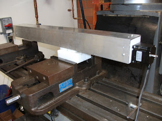
Here's Gulliver's traverse arm upside down, being tested, with the controller box and the Mach3 software I'm using to run it. Artsoft's Mach3 software is a state of the art machine control application, extremely configurable and has a free downloadable version that you can use indefinitely. Highly recommended!


Not too long ago, Gulliver started out as merely a printed circuit board, entirely bare. I forgot to take that picture, so here's Gulliver's "central nervous system" with just the first resistors and capacitors soldered in. This kit is the HobbyCNC Pro Driver Board package, and I can wholeheartedly recommend it to anyone willing to do the soldering and assembly. It's very low cost, high quality and comes with clear directions.

After quite a bit of squinting and soldering later, his main motor controller board is ready.


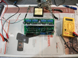
His "central nervous system" is finished up and all four axis motors hooked up and tested.


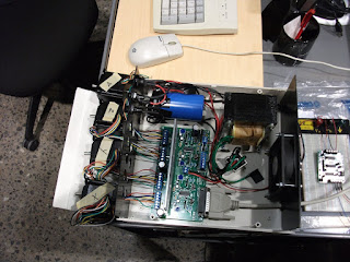
All hooked up, but nowhere to go. Here's the finished motor controller.

Wednesday, April 28, 2010

Repairs and Remakes

All week it's been fixing and shoehorning, shaving down or shimming up. I came up with a novel (for me) way of making small grooves with a hacksaw blade. The students were celebrating that I was going to become rich from my invention until I reminded them that a hacksaw blade costs a buck.

A number of hydraulic motors had to be re-bracketed and re-pulleyed and a hydraulic friction testing piston needed reinforced. So it has gone.


Wednesday, April 21, 2010

PCB Opus 1

In all these years, although I've done minor repair soldering here and there, I'll have to admit to never having populated a PCB with components. I'm beginning work on a pendulum traverse system for one of the professors and decided it was a good opportunity to save several thousand dollars by doing the microcontroller and motor control board from open source hardware. In addition, its a great opportunity to begin creating my first microcontrolled system. I have a backlog of 5 or 6 projects already, this being the simplest!


I'm using an Arduino Deumilanove and purchased Adafruit's Motor Shield, which I highly, highly recommend! The shield comes as a PCB and components and you have to solder them in yourself. The instructions are clear and very complete. I'm fortunate to have been able to simply head over to Radio Shack and buy the tools for a basic soldering setup, and by following the picture by picture instructions, the soldering took less than an hour and the board is running the sample code for DC and stepper motors like a champ.